
10110-6
Rewrite
update
Ray Williamson
Ray Williamson Consulting
January 2009

Status
· I have made some progress on resolving
issues and writing proposed text.
· Reinhold Litscher (sp?) has agreed to
accept assistance on rewrite.
· His group has already begun work on it.
· It will be interesting to see if we pick the
same issues, and similar solutions

My views so far:
PowerPoint doesn't do strikethrough
So...
Black is current text in document
Strikethrough is Blue
My additions are in Red underline
My comments are in Green

3.1
optical system
optical element, subassembly, or assembly
This is vague and allows for circular
definitions later, as in 3.11.
Needs more work.

3.2
optical axis (of an optical system)
theoretical axis about which the
ideal
optical system is nominally rotationally
symmetric
Note: Deflecting elements and systems,
such as plane mirrors, prisms, etc. are
exceptions.
Exceptions to what exactly? Are they to be
defined elsewhere?

3.3
datum axis
axis established by one or more
datum features

3.4
datum feature
Real feature of a part (such as
the outer
edge of the lens cylinder or
a spherical
surface) that is used to establish the
location of a datum.
The datum is the true
geometric counterpart of the datum
feature.
A datum feature should be
accessible and of sufficient size to permit
its use.

3.X (bump all one decimal)
datum
The true geometric counterpart of a datum
feature.

Current 3.5
cylindrical datum feature
datum of a cylindrical surface (such as the
outer diameter of a lens) is the axis of the
cylindrical surface datum feature, which is
the axis of the smallest circumscribed
cylinder that contacts the diameter.
rim
edge of a lens or inner cylinder of a lens
barrel used to establish the cylindrical
datum.

3.x
cylindrical datum
axis of the smallest circumscribed cylinder
that touches an exterior cylindrical datum
feature; alternately, axis of the largest
inscribed cylinder that touches an interior
cylindrical datum feature.
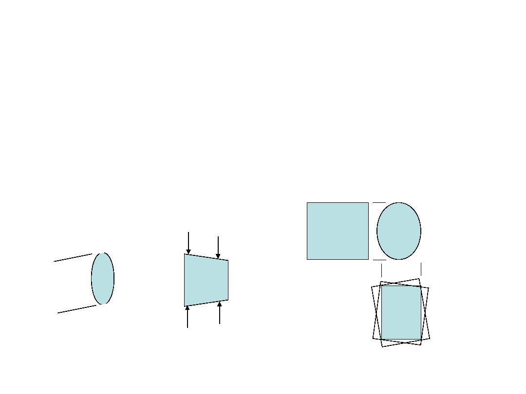
3.5
Sorry, not done yet
· The definition is now clear, but it won't be
helpful in the real world because we have
imperfect cylinders and interacting datums
Two "smallest circumscribed
diameters"
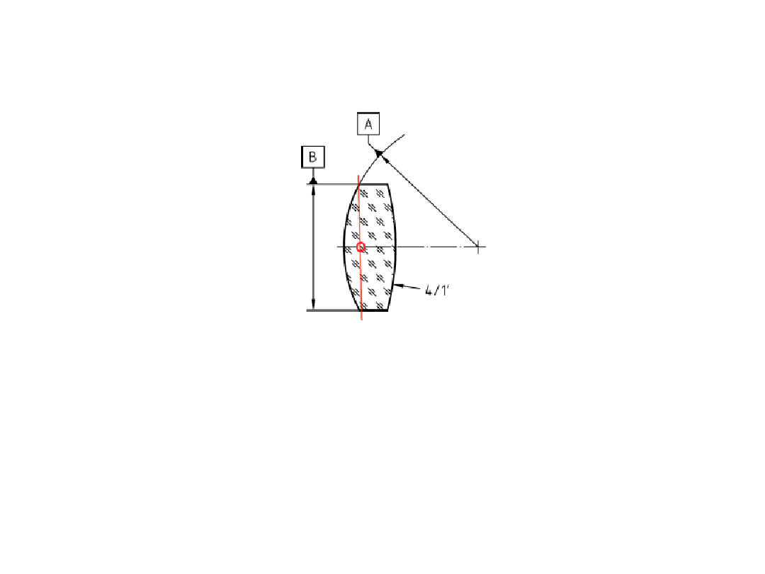
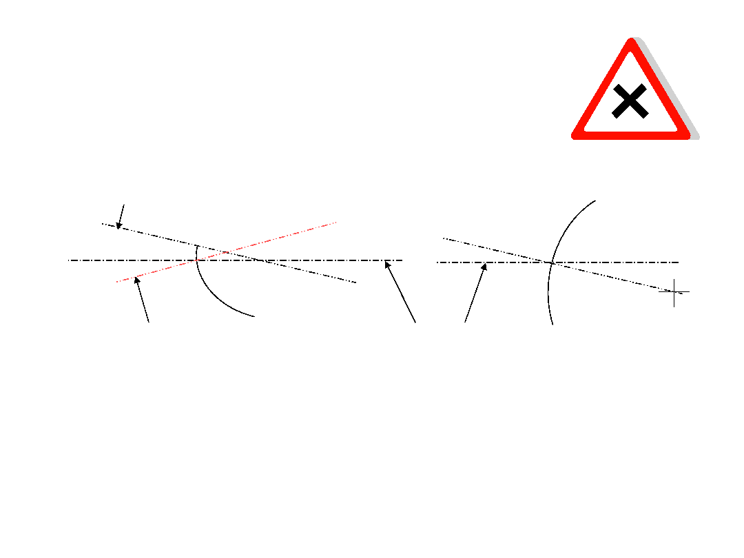
More 3.5:
Geometric impossibility
A
B
No intersection, so
no datum axis exists
.
Yet in practice, lens is fine
4/1'
Reference Figure 5
Why? Datum system is defined by
intersection of center
of curvature of A with axis of B.
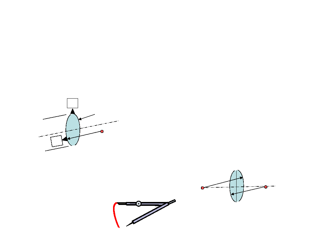
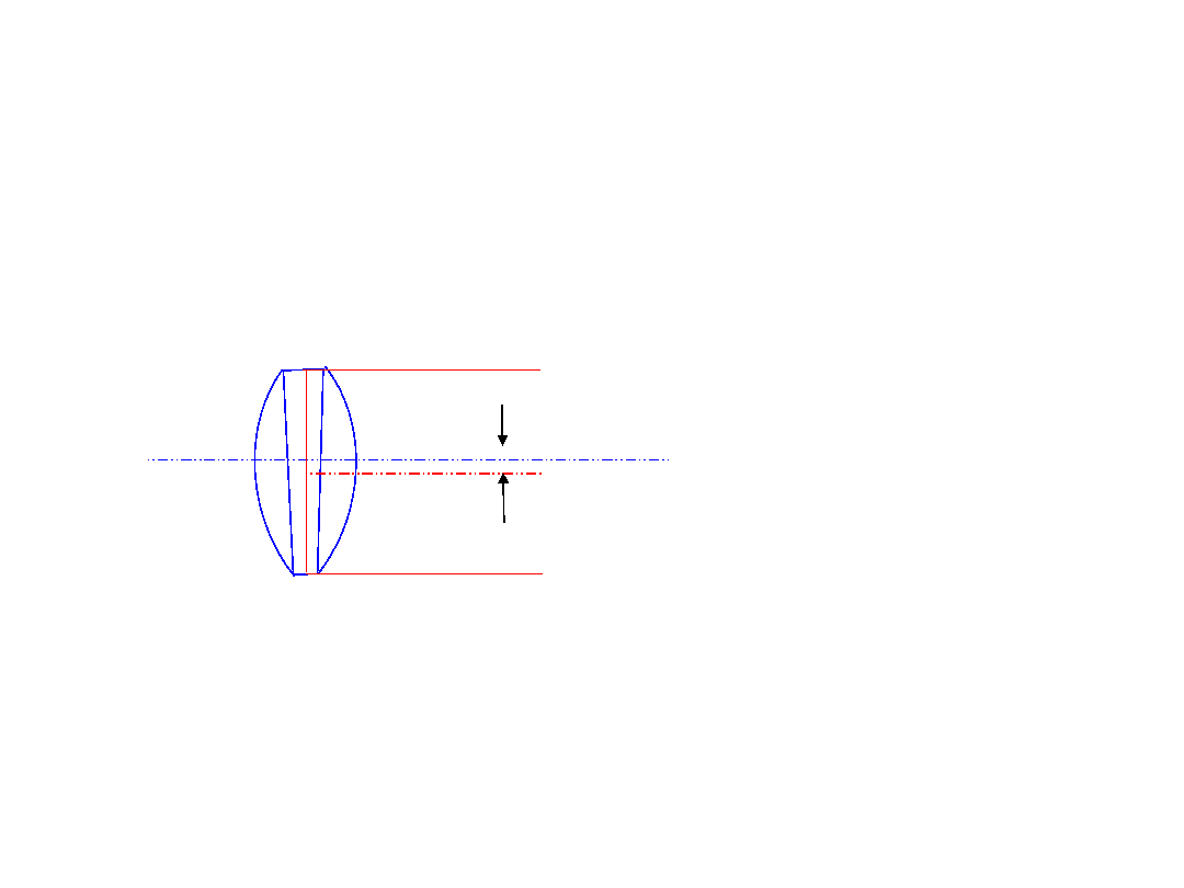
3.5 a proposal
Define cylinder datum to be the center point of a circular
target line at the axial midpoint of barrel edge, unless
another position is specified (as in Figure 4.)
Revise Figure 4 with correct symbol for circular target line
as shown below
Needs more work and discussion
B
As indicated
Where applied
B
B1
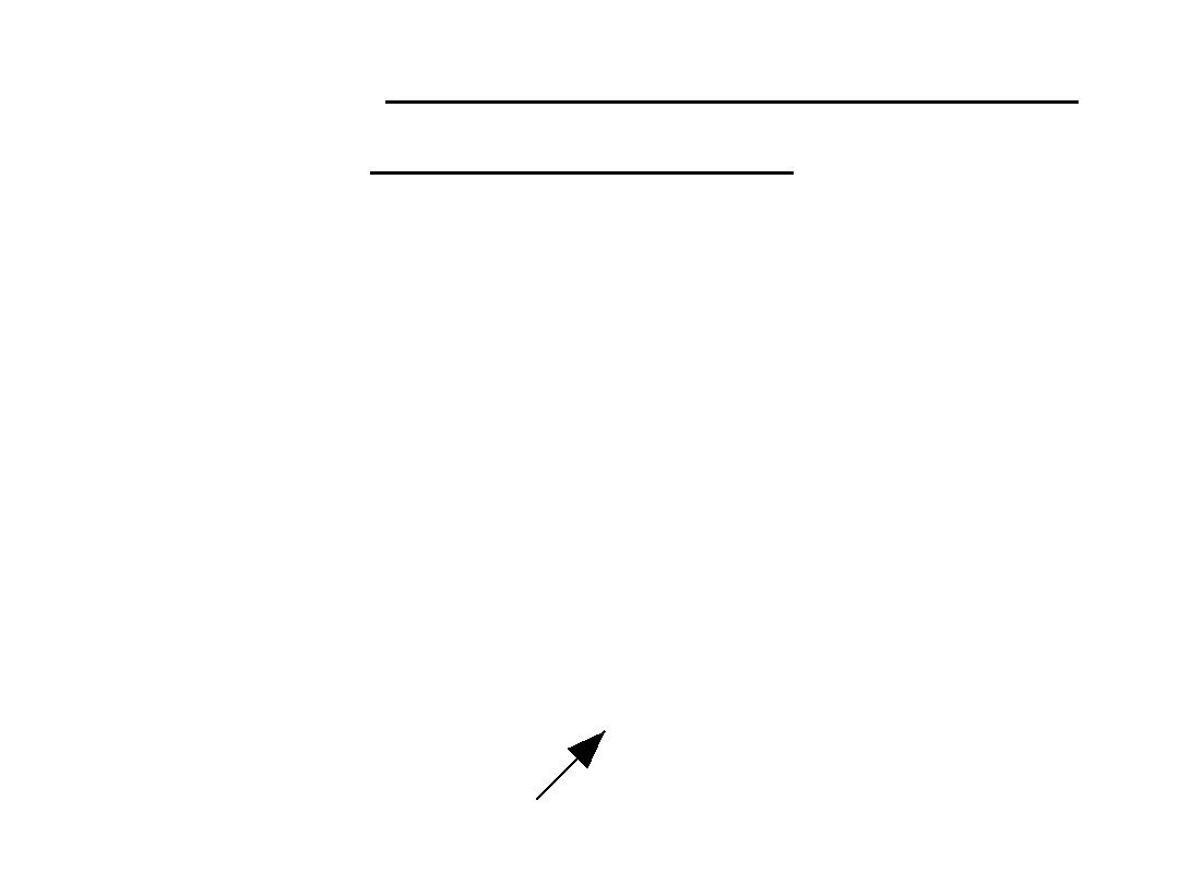
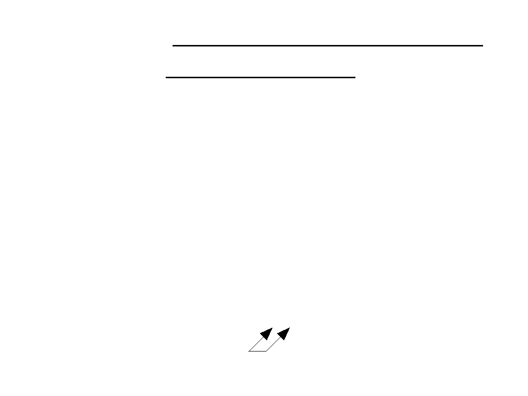
Here's why that's important
We now have two completely
different datum axes
A
a
B
A
B
3.5 alternate proposal
· Chinese comment on figures 5, 6, 7, 9, 12:
"In the DIN 3140-6 (withdrawn) the datum axis was
defined by the centre of curvature and the datum
point on the cylinder axis established by a plane of
the curvature at the cut-section with the outer edge
of the lens cylinder. If the datum point is not in this
plane, define the point (distance a) as in figure 4."

3.6
spherical surface datum
feature
point defined by the spherical surface datum
feature's centre of curvature
3.7
datum point
specified point on the datum axis.
The
location of a datum point must be specified
adequately by dimension lines to other
datum features.
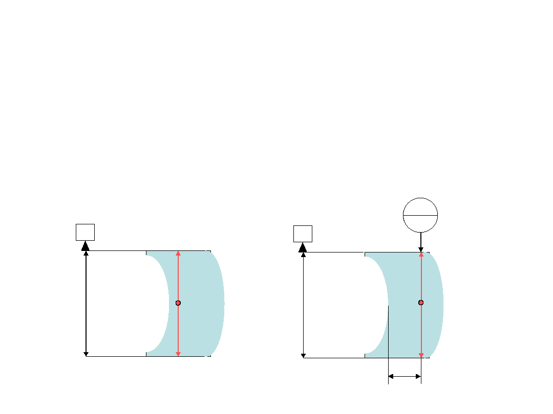
3.9, 3.10
· Both need a figure
1
2
3
L
1 Rotational axis of aspheric surface
2 Aspheric surface
3 Datum axis
Tilt angle of aspheric surface
L Lateral displacement of aspheric surface
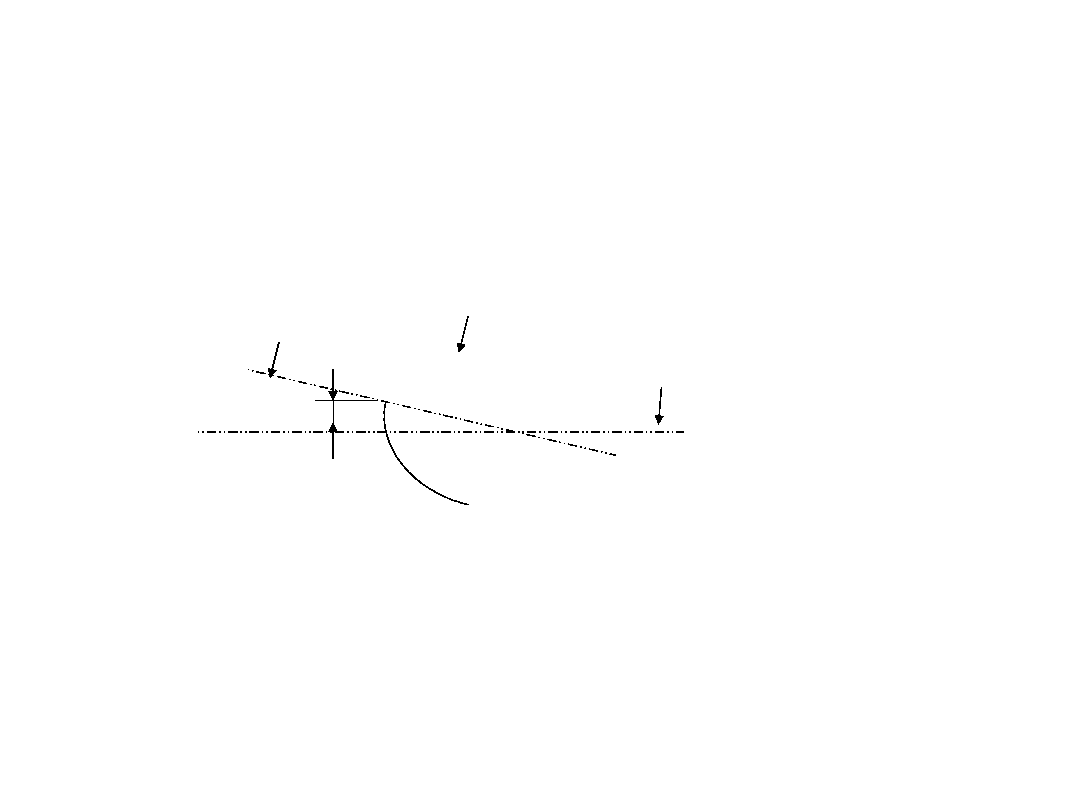
3.10
lateral displacement of an aspheric surface
distance from the
point of rotational symmetry
vertex
of the aspheric surface to the datum axis.
The vertex is the intersection of the asphere's
axis of rotational symmetry with its surface (or
the projection of its surface in the case of off-
axis segments.)
reason: the "point of rotational symmetry" is not
defined, and the intention is different from the
datum of a spherical surface (which is displaced
from the surface by one radius.)

3.11
Tilt angle of an optical element or subsystem
angle between the datum axis of the element or
subsystem and the system datum axis of which
the element or subsystem is a part.
Problem 1: 3.1 defines an optical system as an
optical element, subassembly, or assembly. So
the whole thing is circular and ambiguous.
Problem 2: Now that we're dealing with elements
or subsystems in relation to each other, the
orientation of their tilts and displacements
matter
.

3.11 ctd
We need to better define what is desired
and intended:
1. Tilt between optical axis and datum axis.
2. Tilt between one datum axis and another.
3. A note explaining that the tilt is in the plane
containing the two axes, i.e. the orientation of
maximum tilt value, unless otherwise specified.
4. A note stating that if the orientation of the tilt is
important then the tilt should be specified in
terms of rotations about X, Y, and Z axes in a
separate text note.

3.12
Lateral displacement of an optical
element or subsystem
Distance between the datum axis of the
element or subsystem and the datum axis
of the system which the element or
subsystem is a part, measured at the
datum point of the subsystem.
My head hurts.

Figure 2
I don't see any hint of how the datum point's
position is defined.
Should we have something in the text?
See 3.7 suggestion:
datum point
specified point on the datum axis.
The
location of a datum point must be specified
adequately by dimension lines to other
datum features.

4.2
If the aspherical effect of the surface is small
compared to its spherical power, the
centring tolerance may be specified in
accordance with 4.1, as if it were a
spherical surface.
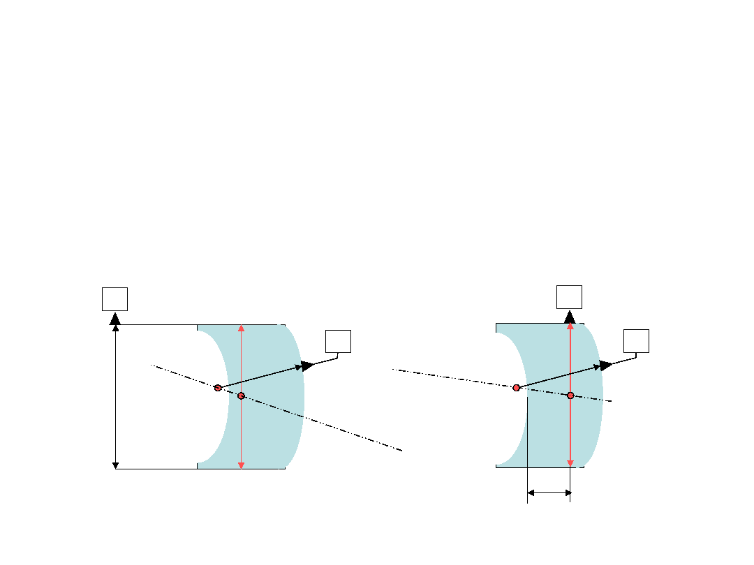
3.8, 4.1, and Figure 1
vs. 3.9 and 4.2
Rotational axis of aspheric surface
Datum axis
Surface normal of aspheric surface
?
When does the aspherical deviation become
"small enough" to switch from one to the other?
We should add an informative note cautioning
about the difference.
Surface normal of spherical surface
(Figure 1.)

5.2
Per Russian comment, replace "point of
symmetry of the surface" with "vertex of
the surface."

5.3.4
...If more than one datum axis is indicated in
the drawing, the reference letters of the
appropriate datum
system
axis
shall be
appended to the tolerance values.

Once around the Maypole
· 3.7 datum point is "specified point on
datum axis."
· 5.2 datum point coincides with point of
symmetry of aspheric surface.
· 3.10 lateral displacement of aspheric
surface is distance from point of rotational
symmetry to datum axis!
Ideas?
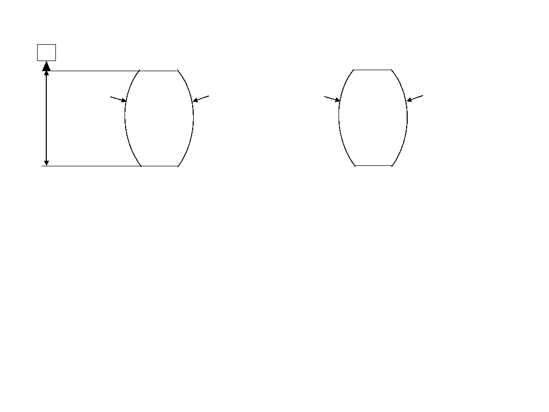
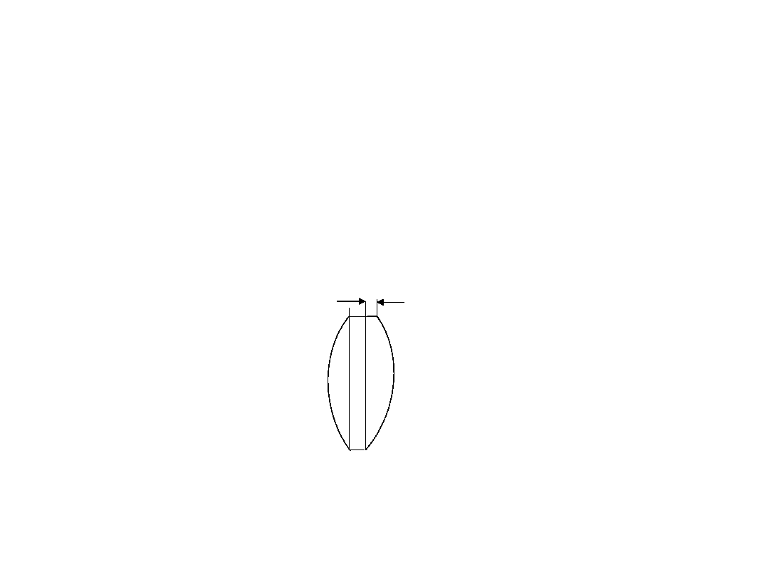
Figure 3
· Impractical for thin lenses: Cylinder edge not "of
sufficient size to permit use." (see 3.4)
· Irrelevant for thin lenses: Few lenses are press-
fit into barrels, and diametral tolerance between
lens and cell makes it meaningless.
· Suggestion: Guide designers to use this form
only for lenses with barrel length >
/2
· Per Chinese comment, delete 3b because it is a
simplification fraught with opportunities for error
A
4/3'
4/2'
4/3'
4/2'
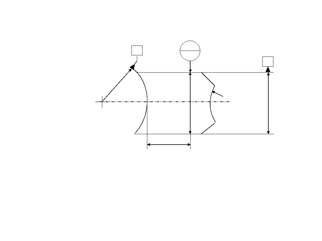
Figure 4
· Legend refers to circular target line B1 but
drawing shows datum B. Indicate B1.
· Remove "C1" on left side of drawing .
B
B1
a
A
4/0,5'
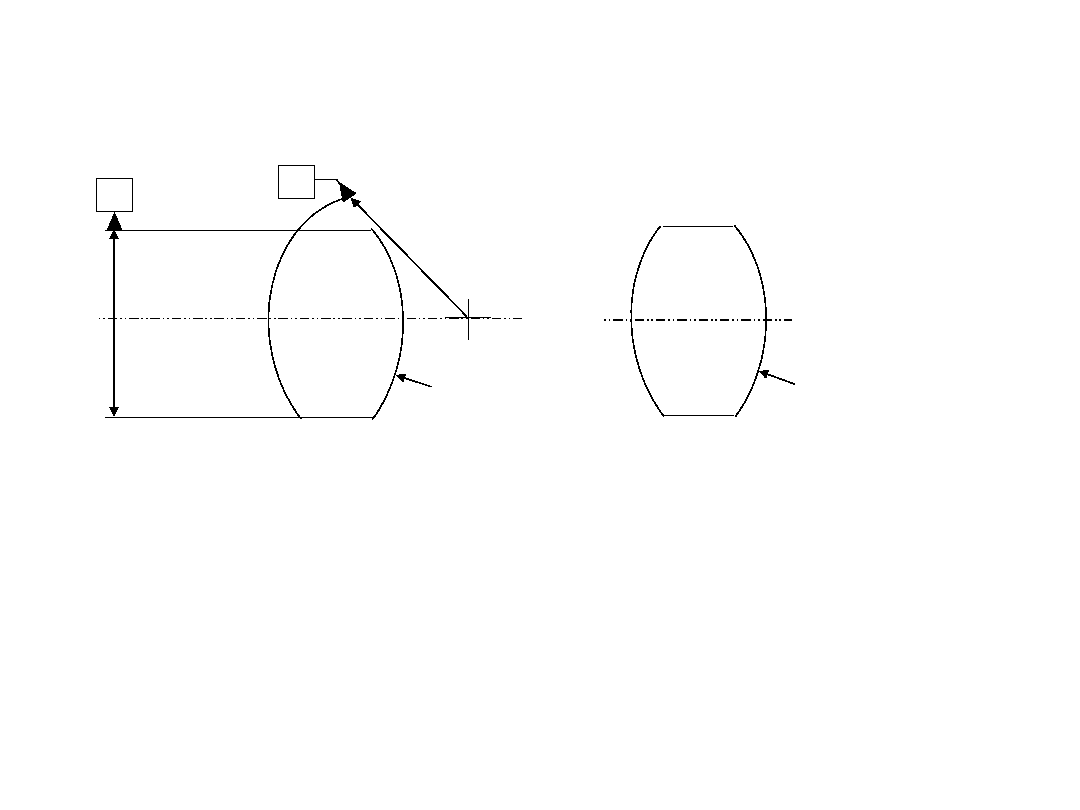
Figure 5
· Per Chinese comment, delete 5b. WAY
too easy to misinterpret even with the
standard in front of you.
B
4/1'
A
4/2'
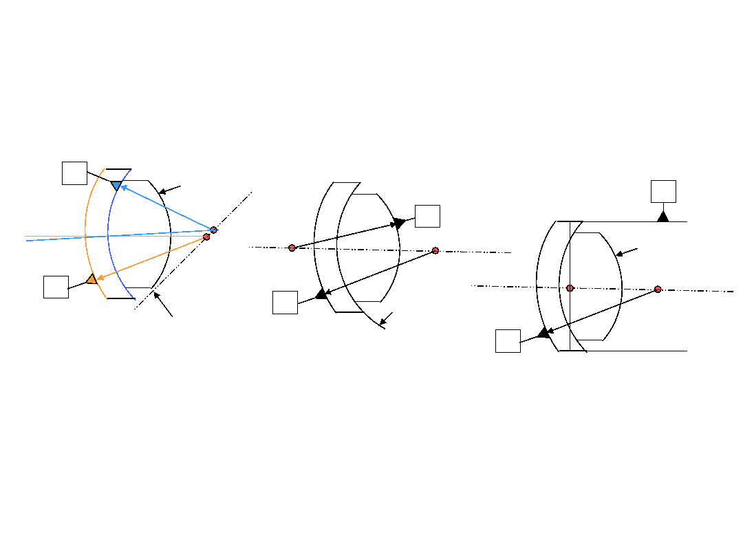
Figure 10 -
A bad example
Don't select two nearly concentric
radii to create a datum axis
Not even tangent!
Better
B
A
A
B
4/3'
4/3'
Better still
A
B
4/3'
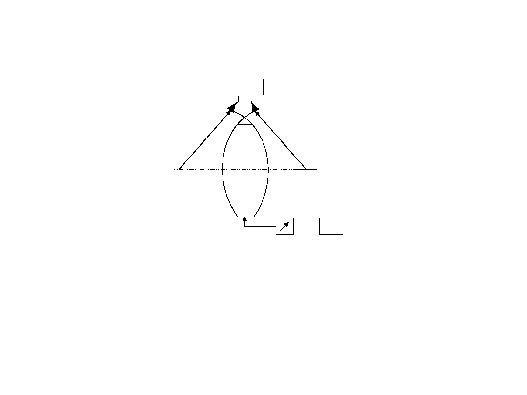
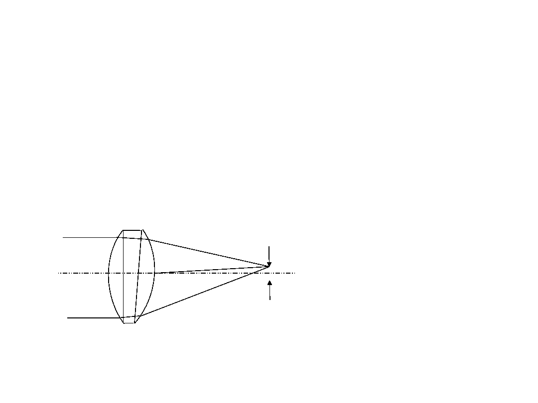
Figure 14
· Legend: "centring tolerance indication for
a surface without optical function"
· Really serves as a good figure for TIR
discussion
A
B
0,1
AB
TIR What is it?
Karow: True Indicator Reading = edge thickness
variation
Willey and Parks: Total Indicator Runout = edge
thickness variation
TIR ctd.
Photonics Dictionary: Total Image Runout =
circular orbit diameter of image from a lens
that is rotated about its rim. (Also total
internal reflection.)
TIR ctd.
Machinists community: TIR 2 X decenter

TIR ctd.
Yoder, Strong, Brown, DeVany, Laikin,
Horne, Kinglsake, Shannon, Zschommler,
MIL-HDBK-14: No mention
Smith, Zemax manual: Total Internal
Reflection (no other mention)
Malacara: No mention (although "decenter"
is defined in terms of the system axis)
Meadows, Geometrical Dimensioning
and Tolerancing:
· Circular Runout: "provides control of circular
elements of a surface. The tolerance is applied
independently at any circular line element as the
part is rotated 360
°
. Where applied to surfaces
constructed around a datum axis, circular runout
may be used to control the cumulative variations
of circularity and coaxiality. Where applied to
surfaces constructed at right angles to the
datum axis, circular runout controls circular
elements of a planar surface (wobble.)"
Meadows, Geometrical Dimensioning
and Tolerancing:
· Total Runout: "provides composite control of all surface
elements. The tolerance is applied simultaneously to all
circular and profile measuring positions as the part is
rotated 360
°
. Where applied to nominally cylindrical
surfaces constructed around a datum axis, total runout is
used to control cumulative variations of circularity,
straightness, taper and coaxiality of a surface. Where
applied to surfaces at right angles to a datum axis, total
runout controls variations of perpendicualrity (to detect
wobble) and flatness (to detect concavity and convexity.)"

TIR summary
· Need to choose one definition
· Need to explain how to convert

The End